Wiring Diagrams
This page is dedicated to Wiring Diagrams that can hopefully get you through a difficult wiring task or just to learn some basics in how to wire a 2-way switch, 3-way switch, 4-way switch, outlet or entertainment component diagrams. If you don't see a wiring diagram you are looking for on this page, then check out my Sitemap page for more information you may find helpful.
Home Electrical Wiring Diagrams
- 2-Way Switch Wiring Diagrams
- 3-Way Switch Wiring Diagrams
- 4-Way Switch Wiring Diagrams
- Outlet Wiring Diagrams
- Dryer Outlet Wiring Diagrams
- Dimmer Switch Wiring Diagrams
- Ceiling Fan Wiring Diagrams
- Thermostat Wiring Diagrams
Home Theater Component Wiring Diagrams
- All-In-One Home Theater Connection Diagram
- Standard TV Connection Diagram
- Plasma/HDTV Connection Diagram
- Standard DVD Connection Diagram
- HD-DVD Connection Diagram
- DVR/PVR/TIVO® Connection Diagram
- Blu-ray Disc Player Connection Diagram
- Satellite/Digital Cable Connection Diagram
- A/V Receiver Connection Diagram
- Surround Sound Connection Diagram
- DTV Converter Connection Diagram
Other Misc Wiring Diagrams
- Relay Wiring Diagrams
- Trailer Wiring Diagrams
2-Way Switch Wiring Diagrams
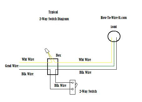
How a 2-Way Switch Works.
The power source is coming in from the left. Notice the black wire is the only wire that we are controlling through the 2-way switch. You have an incoming hot wire (black) going to one screw (it does not matter if you use the brass or silver screw) on the side of the 2-way switch and a black wire from the other screw on the 2-way switch going to the load (light, ceiling fan etc..). The white wires are wire nutted together so they can continue the circuit.
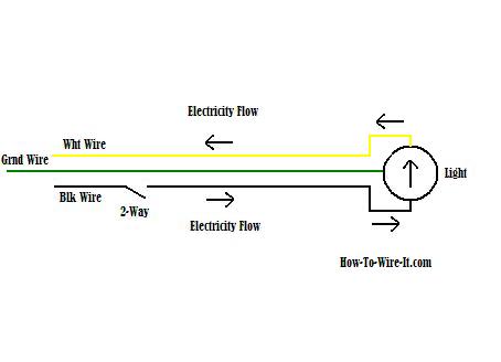
Just use your mouse pointer on this diagram and follow the current flow from black wire (hot wire) through the 2-way switch, then to the load and return through the white wire (neutral). This should give you a good basic understanding how the 2-way switch circuit works and will help you in adding or changing a 2-way switch.
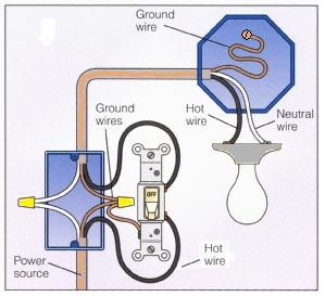
How a 2-way Switch Circuit Looks.
So the circuit above when explained should give you a good concept on how this basic circuit works. When wiring a 2-way switch, this image on the left will show how the connections should actually look when all connections are made. Take notice of the ground wire. It's very important that the ground or bare copper wire is connected to the green screw on the switch. All grounds are connected, and the ground is connected at the light when possible. If no connection is available, then attach the ground wire to the box in a solid way.
3-Way Switch Wiring Diagrams
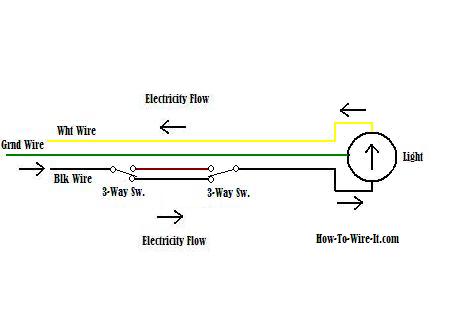
How a 3-Way Switch Works.
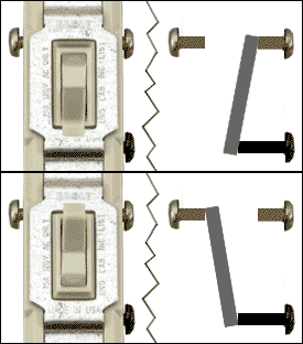
When wiring a 3-way switch circuit, all we want to do is to control the black wire (hot wire) to turn on and off the load from 2 different locations. The diagram here will give you a better understanding how this circuit works and how a 3-way switch is wired. The source power (black wire) is coming in from the left. It ties into the common on the left switch (see image below). When the left switch is toggled, it connects to the upper circuit and now the circuit is open at the right switch which turns off the light. Toggle the right switch and it connects to the upper circuit and now closes the path and turns the light back on and so on.
| | |
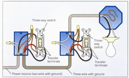
How a 3-Way Switch Circuit Looks.
So the circuit above when explained should give you a good concept on how this 3-way circuit works. When wiring a 3-way switch, this image on the left will show how the connections should actually look when all connections are made.
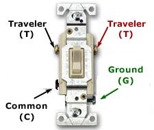
The best way to simplify wiring a 3-way switch is this. By looking at the moving 3-way switch above, the hot (black) wire coming from the power source will always attach to the common screw on the 1st switch in the circuit. The black wire going to the load will always connect to the common screw on the 2nd switch in the circuit. Then the traveler wires are connecting both switches and it does matter which wire goes to which traveler screw. Now with that said, just look at the switch again and look at the circuit. There you have it, 3-way switch wiring simplified.
Take notice of the ground wire. It's very important that the ground or bare copper wire is connected to the green screws on the switches. All grounds are connected, and the ground is connected at the light when possible. If no connection is available, then attach the ground wire to the box in a solid way.
4-Way Switch Wiring Diagrams
How a 4-Way Switch Works.
You must understand the 3-way circuit above in order to get the 4-way circuit. A 4-way switch circuit is nothing more than wiring a 4-way switch between the (2) 3-way switches in a 3-way switch circuit.
Now don't let this be confused with where the switches are physically located in your home. This is how the circuit is structured. The switches can be physically located to your liking but you must keep in mind the ease of routing the wiring from point to point. Also, this example is just adding a single 4-way switch that will give you 3 locations to control your light. To add more locations to this circuit you just simply add additional 4-way switches in series as long as they are between the (2) existing 3-way switches.
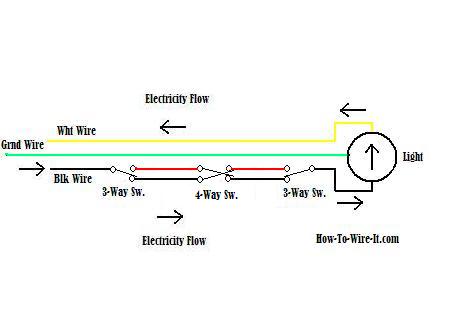
Using your mouse pointer, follow along with me as we go through the circuit. Now this one gets a little tricky by keeping track of what switch you toggle in your mind, just hang in there.
Now the power source (black) is coming in from the left. and goes through the 3-way to the black wire going to the 4-way. Then through the 4-way to the red wire going to the 3-way. Now it dead ends (not connected) which means the light is turned off. By toggling any switch, the light will now turn on. Choose a switch and follow the flow of the switch that changes state. Keep in mind how the 4-way switch works. Left connections toggle between the two right connections. So top left red connects to bottom right black and when toggled top left red connects to top right red. The bottom pole works in the same manner.
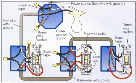
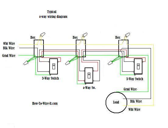
How a 4-Way Switch Circuit Looks.
So the circuit above when explained should give you a good concept on how this 4-way circuit works. When wiring a 4-way switch, this image on the left will show how the connections should actually look when all connections are made.
OK, this diagram is going to be a little more confusing but I'm showing it because this can be a very common scenario. If you notice, the power is coming in at the light box. Because of this, the wiring must be re-color coded in order to get the conductors necessary to complete the circuit. Notice the black power wire in the light box is going to a white wire with electrical tape around it which means the white wire will be used as a power wire or black wire.
Take notice of the ground wire. It's very important that the ground or bare copper wire is connected to the green screws on the switches. All grounds are connected, and the ground is connected at the light when possible. If no connection is available, then attach the ground wire to the box in a solid way.
Outlet-Receptacle Wiring Diagrams
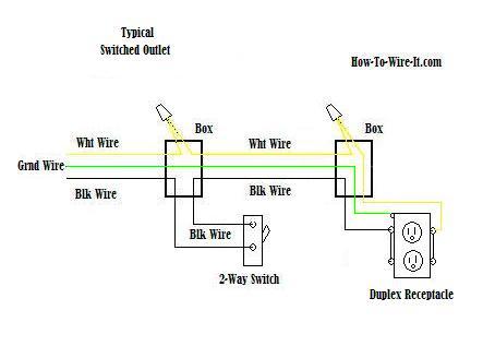
How an Outlet Circuit Works.
The diagram will show how a standard "Switched" duplex receptacle is wired. In this diagram, both top and bottom receptacles are switched off & on. Take notice that only a 3-wire cable is needed to perform this circuit. The white wires tie together to complete the return side of the circuit while the black wire (hot wire) runs through the 2-way switch and out to the outlet.

How an Outlet Circuit Looks.
One of the most common wiring configurations your going to find with outlets are shown in the diagram here. These outlets are not switched. They are connected straight from the power source and are hot at all times. The diagram here shows (2) outlets wired in series and more outlets can be added to this circuit by wiring the 2nd outlet just like the 1st outlet to keep the circuit continuing on until you end the circuit at the last outlet.
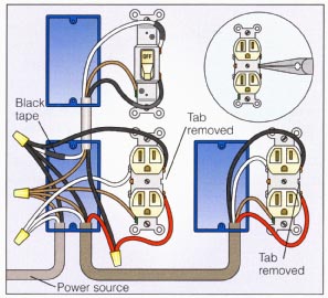
Now lets get a little more involved, in the diagram here we are going to remove the jumpers on one-side of the receptacles. This allows for a separate circuit to be wired to the other screw and allow the upper and lower outlets to work independently of each other.
This circuit allows for the bottom outlet to be switched while the top outlet will remain hot at all times. To perform this circuit with power coming into one of the receptacles, you will need to use a 4-wire cable from receptacle to receptacle which allows for the extra circuit. 3-wire cable into the switch box.
Dryer Outlet Wiring Diagrams
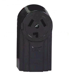
How a 3-Prong Dryer Outlet Circuit Works.
Most older homes are wired for the 3-wire outlet as shown here. The 3-wire connection is now outdated where current dryers are wired with a 4-wire cable. The only difference is the addition of an isolated ground wire separate from the neutral, but the 3-wire circuit is still fine and does not have to be upgraded. You may want to check with your local codes to verify this.
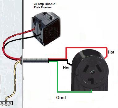
How a 3-wire Dryer Outlet Circuit Looks.
The 3 prong dryer wiring diagram here shows the proper connections for both ends of the circuit. This circuit originates from the breaker box containing a 2-pole 30 Amp breaker. This size breaker requires a minimum of a #10 gauge wire so this wire used would be a 10/2 with ground. If your running a new circuit, I highly recommend that you bring your outlet up to code and install a 4-prong dryer outlet. (See Below)

How a 4-Prong Dryer Outlet Circuit Works.
The 4-wire connection is the new updated circuit. The only difference is the addition of an isolated ground wire separate from the neutral as mentioned earlier.
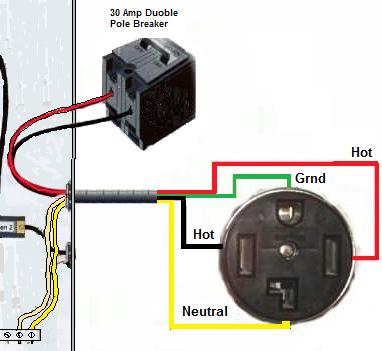
How a 4-wire Dryer Outlet Circuit Looks.
The 4-prong dryer outlet wiring diagram here is ran with a 10/3 with ground cable. As you can see, there is now an added dedicated neutral. The ground is now a dedicated wire also. But if you notice, both the neutral and the ground wires both connect to the same ground bar inside the panel box. As mentioned earlier, the neutral and ground are really the same but this wiring method is more accurate because a return line or "grounded neutral" should be a white wire and not green.
Some panel or breaker boxes will have a dedicated neutral bar and a dedicated ground bar, but they will still be physically connected
Dimmer Switch Wiring Diagrams
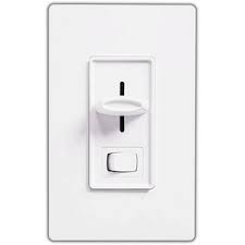
How a Dimmer Switch Circuit Works.
When installing a Dimmer switch, all you're really doing is controlling the amount of voltage flow to a light which makes it dim at a low setting to a fully bright light at maximum setting. You should always make sure the load (Light) is capable of handling a dimmer switch. Some lights will not accept dimmers such as older lights using ballast. These style lights must have full power to operate properly.
Now a typical circuit will contain a 3-wire cable known as romex. (See my Romex Cable page to get familiar with the different types of wire) The cable consist of a black wire, a white wire and a bare copper wire.

How a Dimmer Switch Circuit Looks.
Now in the diagram here, The power source is coming in from the bottom/left. Notice the black wire is the only wire that we are controlling through the 2-way switch. You have an incoming hot wire (black) going to one screw (it does not matter if you use the brass or silver screw) on the side of the 2-way switch and a black wire from the other screw on the 2-way switch going to the load (light). The white wires are wire nutted together and the bare copper grounds are wire nutted together so they can continue the circuit.
Ceiling Fan Wiring Diagrams
How to wire a Ceiling Fan - Light Only.

More often than not, you're going to have a ceiling light fixture at the location you are planning on installing a ceiling fan. If this is the case, then odds are that this old ceiling light only has enough wires to switch off & on the fan or light.
If so then a new wire must be ran to control the light as well. So instead of a 3-wire cable going to the fan, it must be replaced with a 4-wire cable .
When taking down your old fixture you will be able to see if you have the correct cabling. This diagram is for those who are replacing a light fixture with a ceiling fan. Your existing light fixture was controlled by a switch and only one switch. Chances are, you only have a 3-wire cable ran to the fixture so you would be limited to powering the ceiling fan & light both. Typically using the switch for the light and turning the fan on/off by the fan switch on the unit (pull chain). Of course this is all based on not replacing the existing wiring that you currently have.
How to wire a Ceiling Fan and Light.
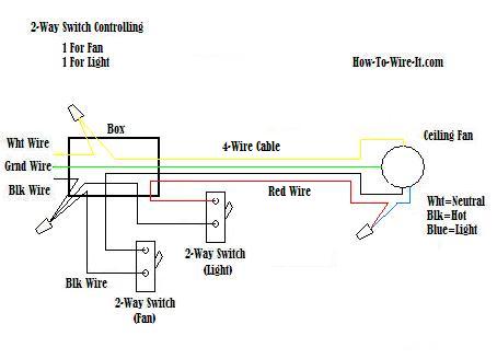
Two switches at one location. One 2-way switch that turns on/off the light and one 2-way switch that turns on/off the fan.
Maybe you are just replacing an old ceiling fan with a new one and you already had (2) separate switches. One controlling the light and one controlling the fan. Then this should look like your connections.
How to wire a ceiling fan and light with a 3-way switch circuit .
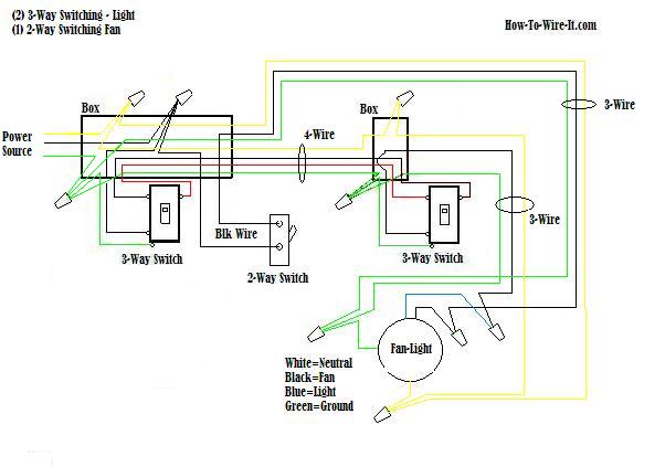
Now for the good one. In the diagram above, you can turn on/off the light from 2 different locations. The fan is operated from one location. The 3-way switches are for turning on/off the lights and the 2-way switch is for turning on /off the fan . This can be a complicated circuit only if you make it one, but if you just keep in mind that the basic circuits discussed above is the same as this circuit, it's just 2 different type circuits combined. One circuit controlling the lights and one circuit controlling the fan.
Thermostat Wiring Diagrams
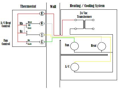
The diagram here shows how a basic 4-wire thermostat is connected as indicated by the color code chart below. The basic Heat + A/C System thermostat typically utilizes only 5 terminals.
RC - Red Wire (Power 24 Vac)
RH or 4 - Red Wire Jumpered (Power 24 Vac)
W - White Wire (For Heating Enable)
Y - Yellow Wire (For Cooling Enable)
G - Green Wire (Controls Fan ON-Auto)
The diagram shows how the wiring works. However your connections may seem a little different on the thermostat itself. The RED wire or 24 Vac power lead is connected straight to the RC & 4 terminals. Some thermostat units have a dedicated R terminal and it jumpers to the RC, RH or 4 terminals internally. The W, Y and G terminals should be pretty straight forward on most all types of thermostat's.
Relay Wiring Diagrams
How a Relay Circuit Works.
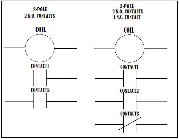
A relay is basically a switch but not like a switch that's on a wall. A wall switch relies on someone to flip it which will then control a light or some other type load. A relay is switched by electrical power and not a human. This is done by energizing a coil which is internal to the relay and by energizing the coil, the relay changes state just like a wall switch would. Therefore when you energize a relay, you are switching circuits off and on. The contacts shown in the Relay Contact diagram shows 2 different type relays. The left is a 2-pole relay and the right is a 3-pole relay. When the relay coil is energized, the contacts change state. The N.O. (normally open) contacts become closed and the N.C. (normally closed) contacts become open. This allows separate circuits to be controlled by 1 or more relays.
How a Relay Circuit Looks.
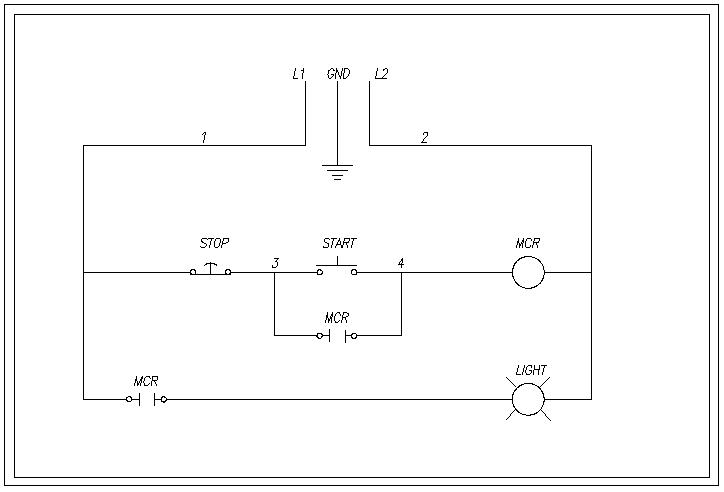
Let's just say we are using 120Vac household voltage in this diagram. L1 is hot and L2 is neutral. So as you can see, L1 goes down into a normally closed "STOP" switch. This means the current travels through that switch until it see's an open switch and cannot go any further. In this case L1 is hot all the way to the "START" switch and the open MCR contacts. When the start switch is depressed, L1 is now hot to the relay coil MCR (Master Control Relay) and energizes the coil. Now the (2) MCR contacts which are normally open as shown will now close. This allows current flow through the contacts and energizes the light. Now that the contact below the START switch is closed and current can go around the start switch, you can now release the START switch and the current flow continues around the open START switch, through the contact to keep the relay coil energized which also keeps the light on. Now to turn the light off, you simply depress the STOP button and this will open the circuit to the relay, de-energizing the coil. The relay contacts open to their normal state and stop the current flow to light. Once you let off of the STOP button the circuit is back to it's normal state with L1 waiting for the START button to be depressed.
Trailer Wiring Diagrams
Trailer 4-Pole Circuit.
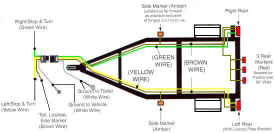
When wiring your trailer, be sure to route your wiring so that all wires are tucked in and away from anything that could rub or catch on them. If your trailer is constructed of square tubing, I find that running your wires through the inside of the tubing makes for a much cleaner appearance and helps to protect the wiring as well. If your frame does not have pre-drilled holes, then it might be a little bit more work drilling holes and fishing out your wires, but you will be much more happier with the results. Be sure to seal your holes when done to prevent water from filling up your frame.
If you have a U-Channel or angle iron construction, then you can purchase specially made clips from most automotive stores that attach to the frame which will keep your wiring tight inside the frame and out of the way.

4-Way Trailer Socket.
This socket is wired to the vehicle circuit to eliminate the hot wires from being exposed which could short out against other metal objects it could possibly touch. Only the ground post is exposed.

4-Way Trailer Plug.
This plug is wired to the trailer circuit. The exposed post are never hot until they are plugged into the socket, therefore it doesn't matter if they are exposed. Only the ground post is protected and acts as a key so it fits into the proper socket.
Trailer 6-Pole Circuit.
| 6-Way Trailer Socket. | 6-Way Trailer Plug. |
Trailer 7-Pole Circuit.
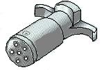
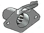
| 7-Way Trailer Socket. | 7-Way Trailer Plug. |
7-Pole Trailer Pin-out Diagram

Posted by: rowenawhapt1951esz.blogspot.com
Source: https://www.how-to-wire-it.com/Wiring-Diagrams.html
